G-UFOX
- Controls (Stuff We Have Learnt)
The controls are a fundamental part of
the plane that you don't want to get wrong.
Lay the tubes out first.
Dry-assemble the parts until you can get
it all aligned, before taking apart again to put the loctite on.
Just because all the other parts you have
come across have been suitably reamed, do not assume that they all are.
The nylon mounting blocks for the main
control tube need to be fettled to get a smooth operation of the elevator. When
you clamp these down they can spread very slightly and tighten between the lugs
on the tube, so once again it is an iterative process. Rub the sides down on
fine emery paper (always both halves together) until the elevator is low friction
(even when bolted down), but not too much so that there is axial play on the
tube. Mark them first to ensure you always have the same block in the same orientation.
Getting the foot peddle mounts through
the carpet and fixed through the floor can be fun. Ensure the nylon bushes are
a smooth fit in the tubes, are greased (silicon) and firmly fixed to the brackets
(you want the tube to rotate around the bush, rather than the bush twisting
on its mounting bolt. Also check for endfloat - we had to add a large penny
washer to reduce this.
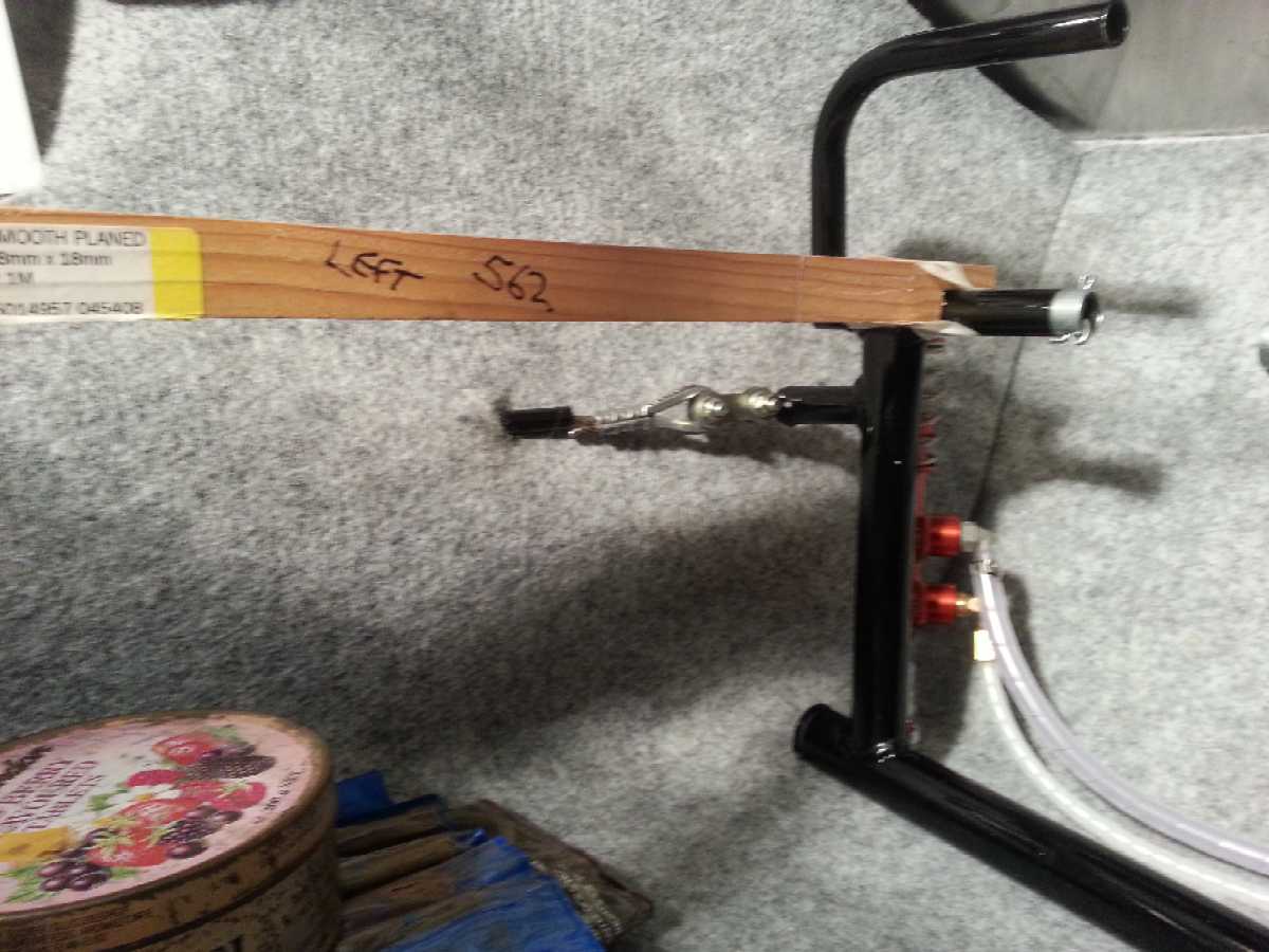
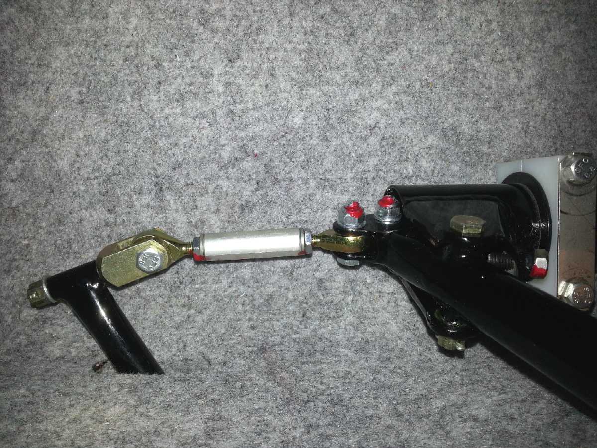
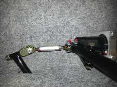 The
short aileron control links between the control tube and the first belcrank
may need special attention. On ours, when the joystick was fully back and to
one side, there was little clearance between the rose joint and the bronze coloured
clevis on the belcrank. This is due to the height difference. Adjust the angular
relationship between the two rose joints, so that there is small rotational
movement of the link available over the full range of the joystick.
The
short aileron control links between the control tube and the first belcrank
may need special attention. On ours, when the joystick was fully back and to
one side, there was little clearance between the rose joint and the bronze coloured
clevis on the belcrank. This is due to the height difference. Adjust the angular
relationship between the two rose joints, so that there is small rotational
movement of the link available over the full range of the joystick.
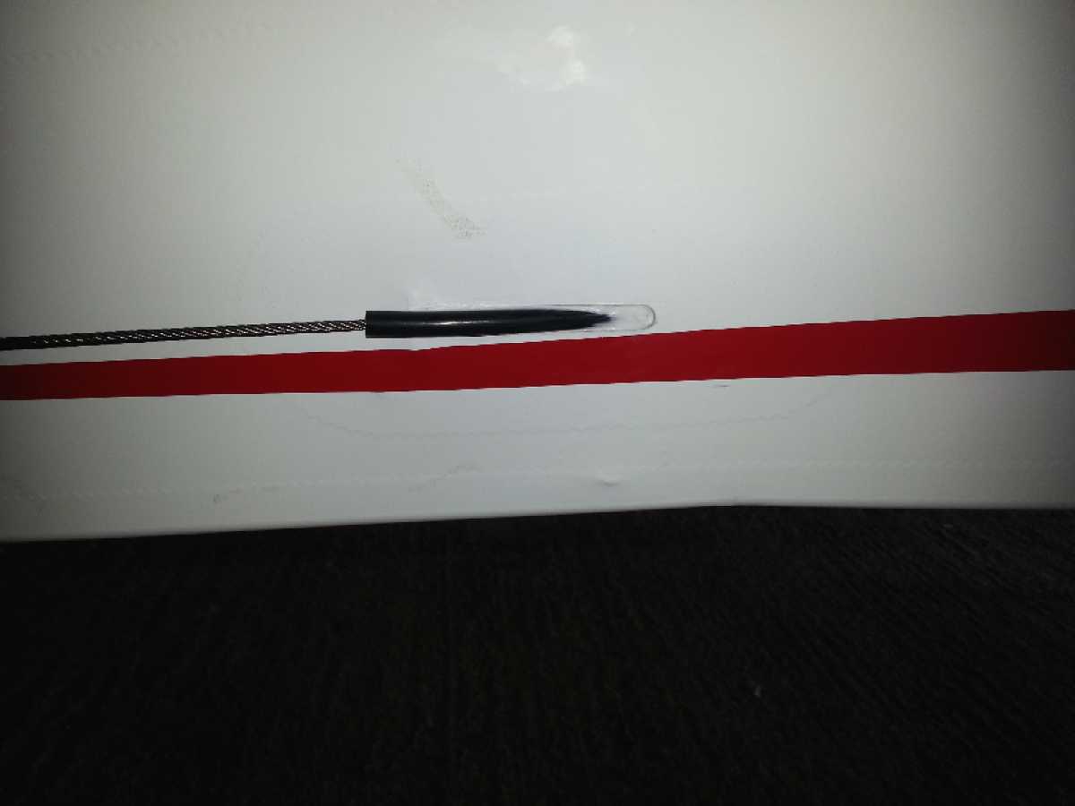
 The
rudder cable tubes may need to be cut back in the cockpit, to give adequate
movement of the peddles. Remove the cable first as you MUST NOT damage a single
cable strand or the cable will have to be replaced. Before extracting the cable,
attach a bit of string or wire to the end, that can be used to pull the cable
back down to the rudder end - important as the tube is not complete, but has
gaps along it's length.
The
rudder cable tubes may need to be cut back in the cockpit, to give adequate
movement of the peddles. Remove the cable first as you MUST NOT damage a single
cable strand or the cable will have to be replaced. Before extracting the cable,
attach a bit of string or wire to the end, that can be used to pull the cable
back down to the rudder end - important as the tube is not complete, but has
gaps along it's length. 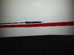 Don't
forget to put the heatshrink on the cable before crimping the rear rudder ferrule.
Use
some silicon rubber around the point where the cable tube comes out of the rear
fuselage to protect the wood from water.
Don't
forget to put the heatshrink on the cable before crimping the rear rudder ferrule.
Use
some silicon rubber around the point where the cable tube comes out of the rear
fuselage to protect the wood from water.
The extent of downward movement of the
elevator and movement of the rudder are not adjustable. So these will have to
be good enough.
We originally used fuel pipe for the flap
control
end-stop rubbers. We were advised to use something thinner to give a slight
extra movement, so we used the yellow tygon tube.
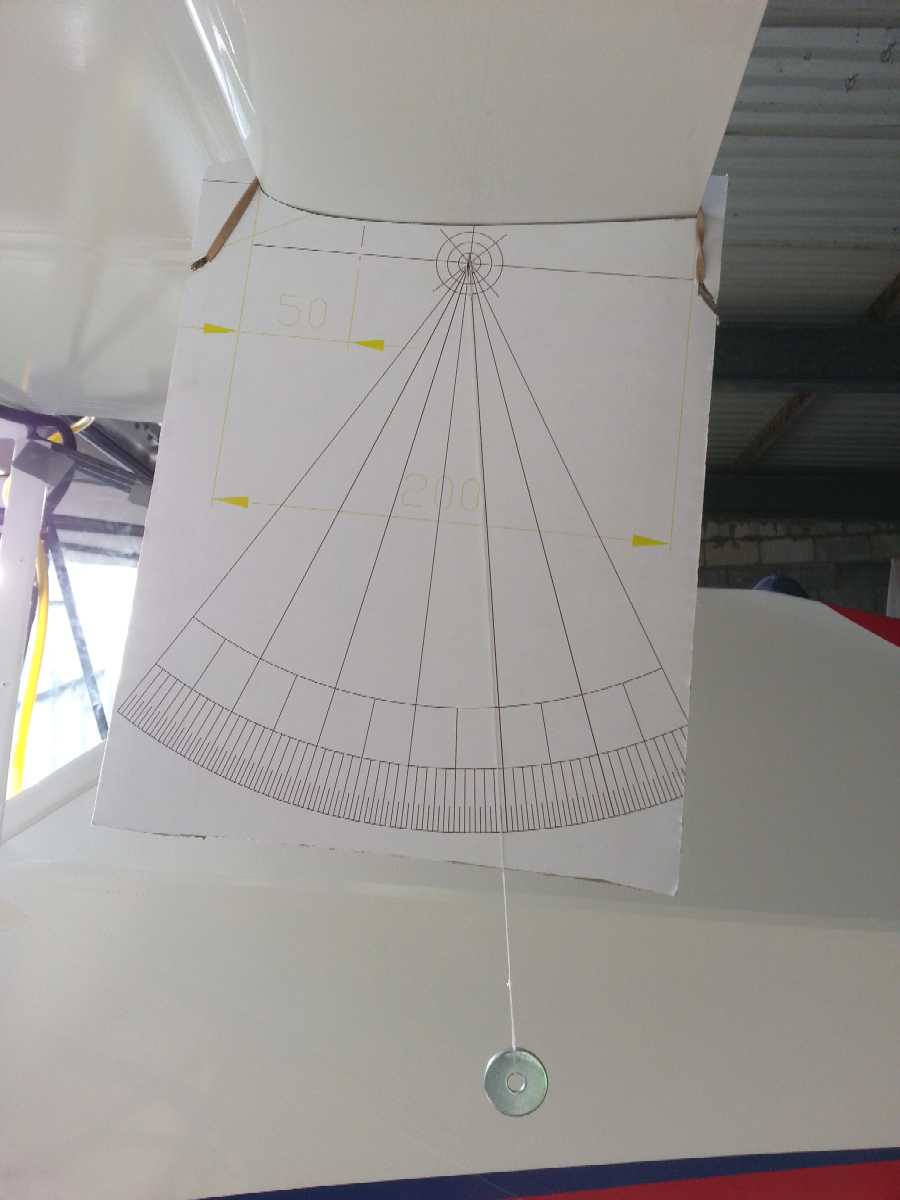
Measuring deflections
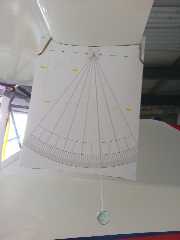 The
flapperons deflections are the ones with the tightest tolerance. I made a large
protractor by printing out an autocad file (or
pdf) and sticking it onto cardboard. The top is
profiled to match the flapperon and can be held on with elastic bands. A small
pivot point is made from a paperclip and a pendulum from a couple of large washers
on thin string (dental floss). Sounds weird, but it does work.
The
flapperons deflections are the ones with the tightest tolerance. I made a large
protractor by printing out an autocad file (or
pdf) and sticking it onto cardboard. The top is
profiled to match the flapperon and can be held on with elastic bands. A small
pivot point is made from a paperclip and a pendulum from a couple of large washers
on thin string (dental floss). Sounds weird, but it does work.
First, you need to set the neutral position.
Use some longer M6 grubscrews (25mm I think) in the joystick adjusters to lock
the aileron control central. Set the flaps to neutral and adjust the flap control
to mixer pivot bar to a length that looks right - bit of a guess really. The
templates provided allow you to set the length of the short link to the first
(forward) belcrank and then the other to set the length between the two belcranks
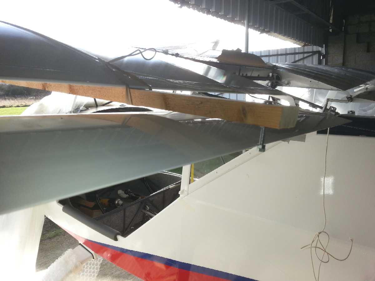
(forward to back). Then adjust the length of the link from the rear belcrank
to the flapperon to set the flapperon trailing edge to exactly 46mm below the
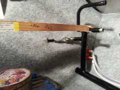
wing (see diagram). 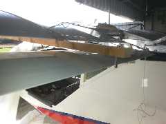 I
used a thin batten of wood with a bolt and nuts to mark a point 46mm below the
top surface of the batten. This is held to the underside of the wing with elastic
- ensure it is straight by lining it up with a rib.
I
used a thin batten of wood with a bolt and nuts to mark a point 46mm below the
top surface of the batten. This is held to the underside of the wing with elastic
- ensure it is straight by lining it up with a rib.
Use your protractor and note the neutral
position. Apply full flap and measure the deflection (change in protractor reading).
Back to neutral flap, and set the aileron flap stops - remove the temporary
longer grubscrews and fit the correct ones (20 mm) and locknuts. Adjust the
endstops to get the correct aileron deflections and lock the nuts.
The elevator and trim tab deflections
I measured with a level gauge app on my phone. The rudder deflection was measured
rather coarsely using a compass app, but you need a wooden (or non-ferrous)
spacer between the rudder and the phone. You are somewhat limited on what adjustments
you can make with the rudder and elevator.
Return to "Stuff
We Have Learnt" page
Return to main index page
 The
short aileron control links between the control tube and the first belcrank
may need special attention. On ours, when the joystick was fully back and to
one side, there was little clearance between the rose joint and the bronze coloured
clevis on the belcrank. This is due to the height difference. Adjust the angular
relationship between the two rose joints, so that there is small rotational
movement of the link available over the full range of the joystick.
The
short aileron control links between the control tube and the first belcrank
may need special attention. On ours, when the joystick was fully back and to
one side, there was little clearance between the rose joint and the bronze coloured
clevis on the belcrank. This is due to the height difference. Adjust the angular
relationship between the two rose joints, so that there is small rotational
movement of the link available over the full range of the joystick.