G-UFOX - Wiring and Panel (Stuff We Have Learnt)
The starter motor
take a lot of current so good conductivity is
essential.
BEFORE
fitting
the engine
onto the mounting frame,
clean the paint from the inside of the bolt hole tubes, to get a good earth
from the engine to the frame. Similarly
clean the lug for the short earth lead that connects to the starboard-most frame
mounting bolt (I know this is much harder once the engine is fitted to the firewall)
and the hole on the main chassis on the other side of the firewall. Also clean
the lug for the battery earth cable. 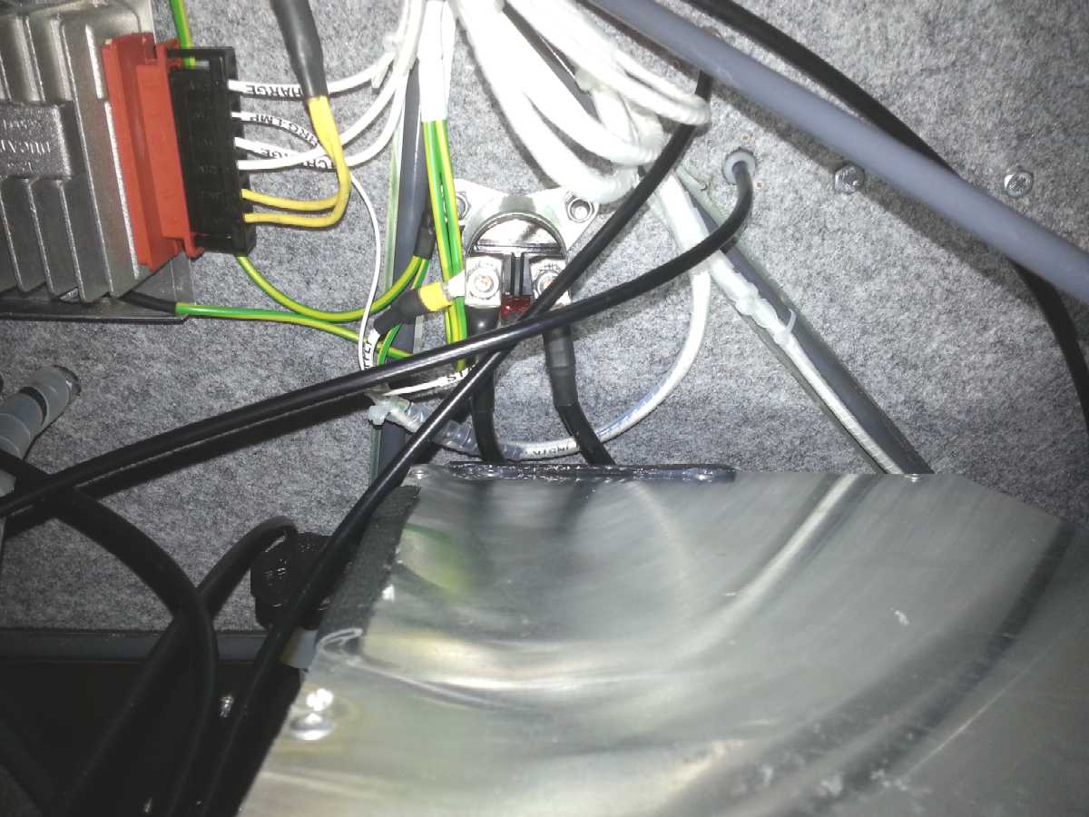
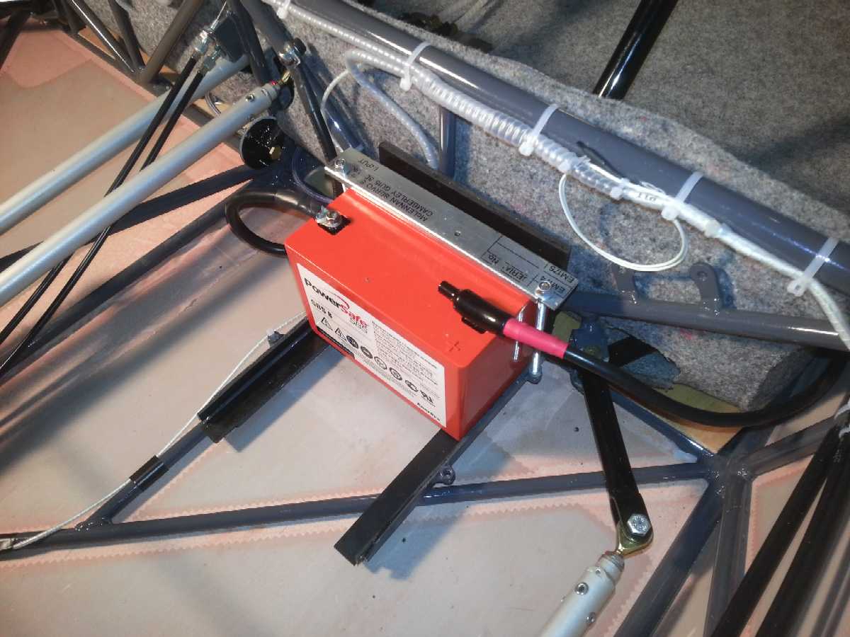 Put
a rubber boot over the positive battery connection (I used a boot for a fuseholder
and cut a small square hole in the side). The thick leads to the starter solenoid
will need to be carefully bent back towards the firewall to prevent them rubbing
on the rear of the glovebox - add a little trim aswell to prevent abrasion.
Put
a rubber boot over the positive battery connection (I used a boot for a fuseholder
and cut a small square hole in the side). The thick leads to the starter solenoid
will need to be carefully bent back towards the firewall to prevent them rubbing
on the rear of the glovebox - add a little trim aswell to prevent abrasion.
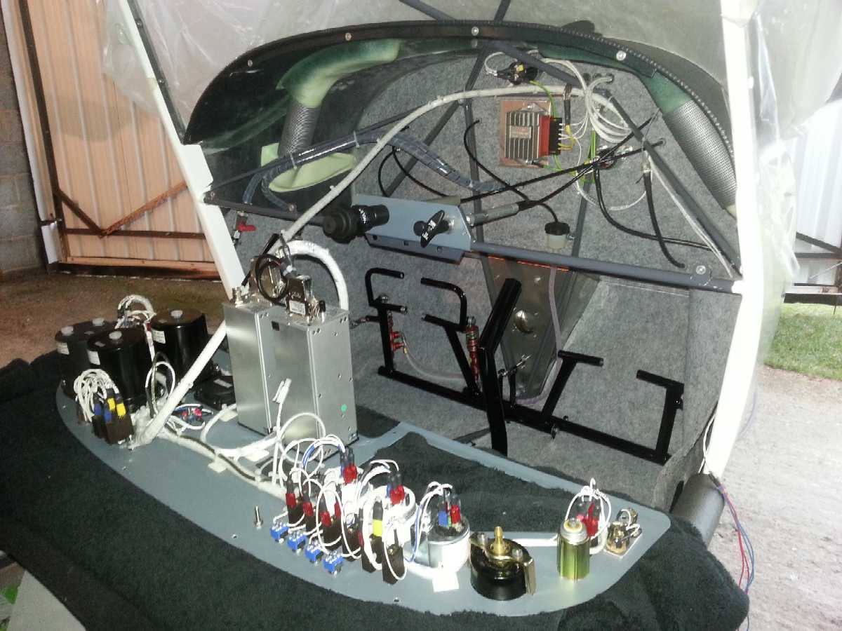
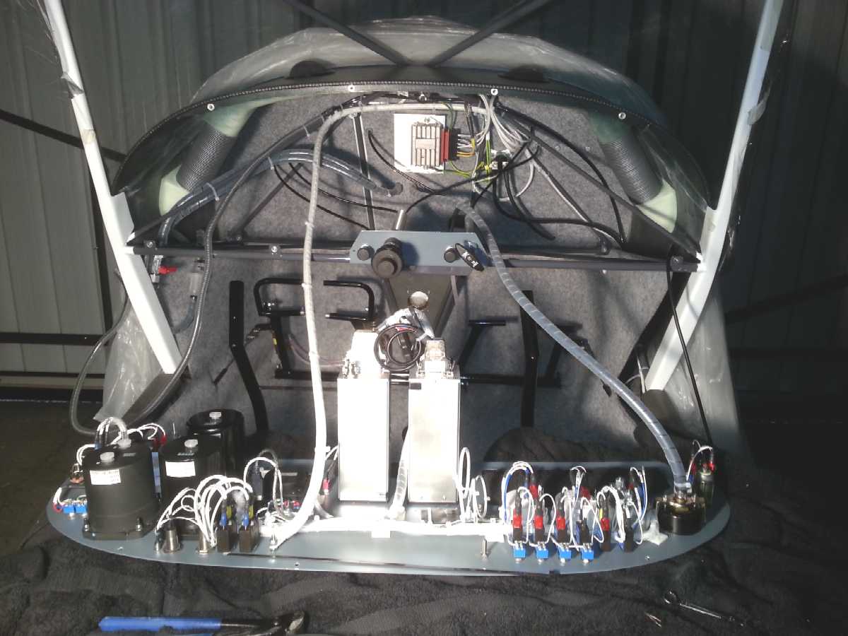
Sort out your wiring diagram. I believe that the EuroFOX supplied diagram is incorrect - the C42 wiring diagram is also wrong in the same sense. The Rotax manual states "Never sever the connection between terminal C and +B of the regulator (e.g. removal of fuse) while the engine is running. Overvoltage and regulator damage can occur." If you use the EuroFOX standard wiring diagram you could do this by accidentally switching the master switch off whilst the engine is running (I know you shouldn't do this, but accidents can happen). I chose something similar to the one in the Rotax installation guide. I have also added 25A breakers in the charging circuit (as recommended by Rotax) and also one in the main supply feed from the battery.
A newer type of oil pressure transducer was fitted to our engine. A bit of research (and help from Roger/Adrian/Nick and ConAir Sports) and I got the pinout data (and other info) here. It is a 4-20mA current device. I also have the data on the oil pressure gauge and oil temperature gauge (from Road Deutchland www.road-online.de) - yours may not be the same!
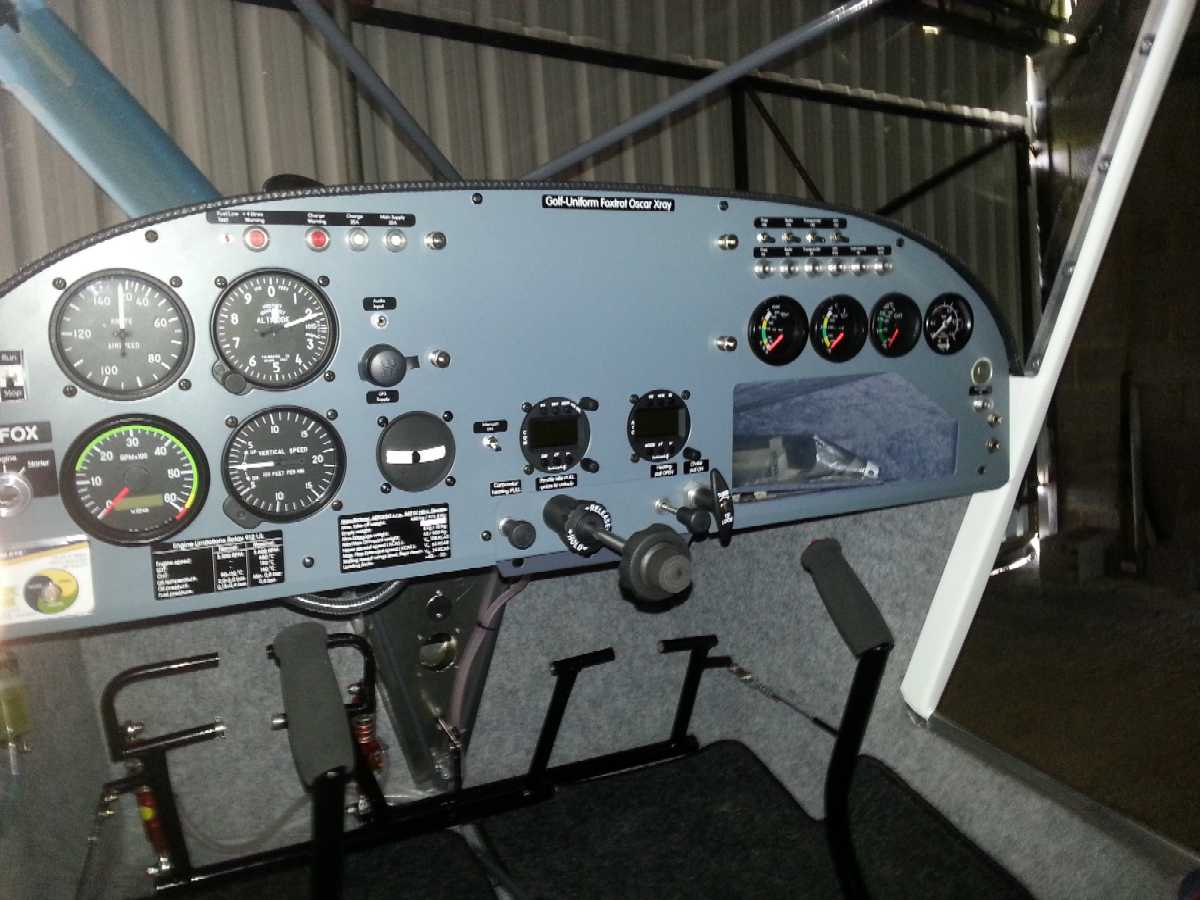
The panel is supplied pre cut with holes, but they may need fettling which should be the first job for the panel (before attempting to screw bits on it). We used the lovely Funkwerk radio and transponder. The screw holes for the radio that have control knobs within them, are larger and will need enlarging.
When buying the wire, we have been recommended to use aviation quality wire - I got ours from Airworld. Work out how much you need giving plenty of extra for the looming, ends etc. Then buy three times as much! You will be amazed and it is much better to snip some off, than to find you can't get it to reach. Scrimping is false economy.
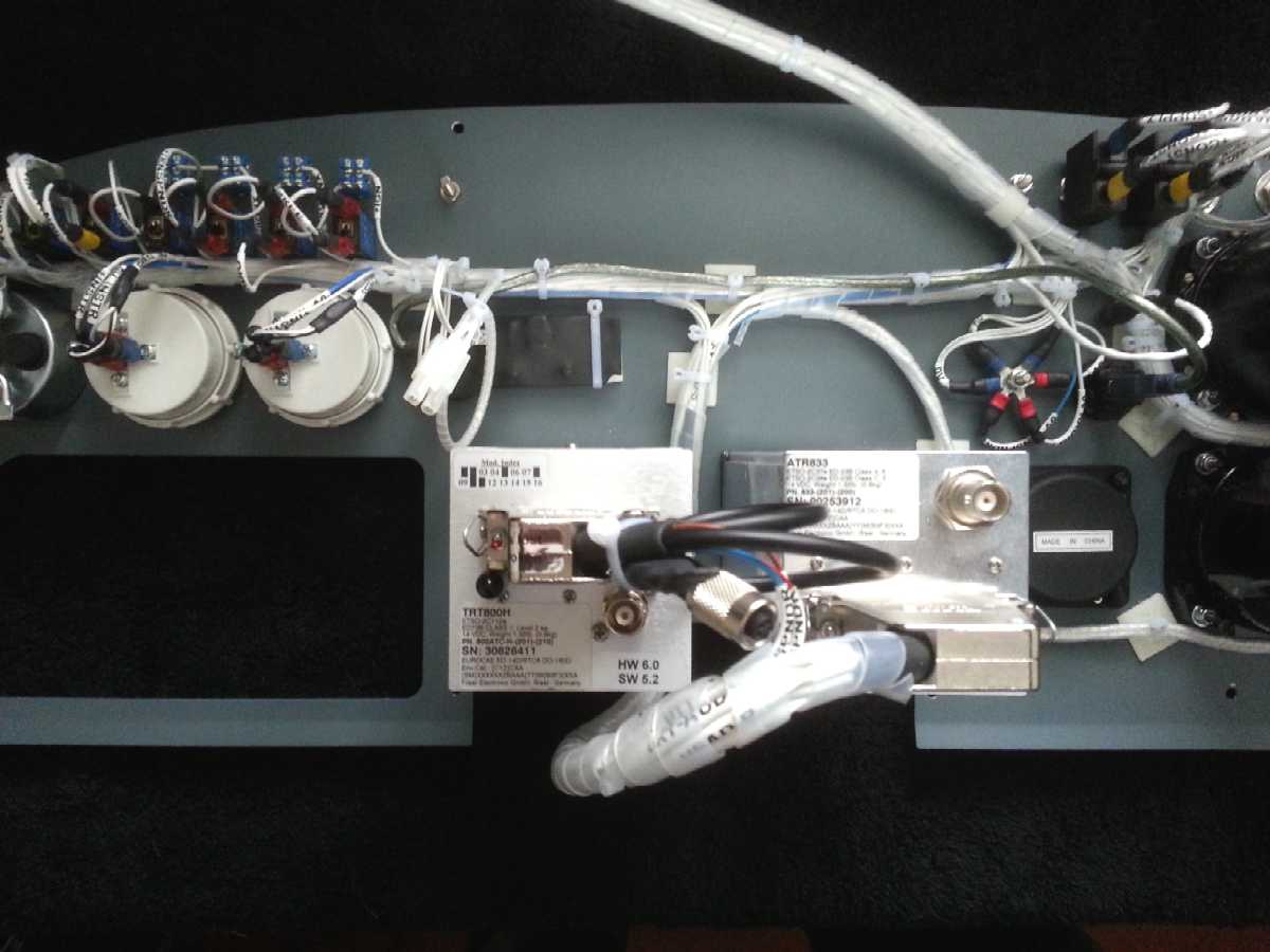
 I
wired
the panel at home and made a long umbilical bundle to connect all the signals
to the airframe. This allows the panel to easily be removed and rested on the
seats if you have to do work behind.
I
wired
the panel at home and made a long umbilical bundle to connect all the signals
to the airframe. This allows the panel to easily be removed and rested on the
seats if you have to do work behind.
Wiring to the MAGS / engine kill switches should be made with screened wire. These go into the remaining empty contact of the ignition control units, with a little rubber bung (provided) to seal it. If you have a 100hp ULS engine, it will come with soft-start ignition modules fitted and you will need to connect an extra wire from the starter switch. I used screened wire for all the engine signals to prevent noise pickup. Check that the wiring in the engine bay will not rub on any edges that may cause abrasion - particularly the braided cables on various bits of the engine frame.
I also used a separate ground (0V) lead from the instruments to chassis, to prevent changing loads from affecting the instrument readings.
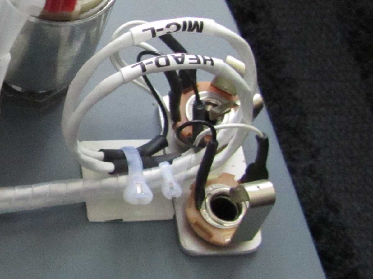 I
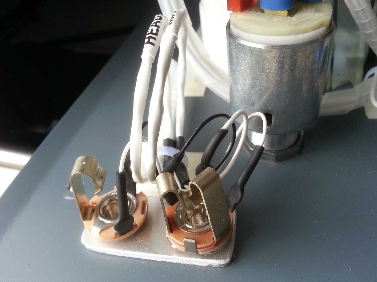
used screened cable for the radio signals. Our headset sockets are on the panel
- I made some extra packing panels out of 1.6mm aluminium to go behind the panel
- these not only allow the non rotation washer to be fitted, but also make the
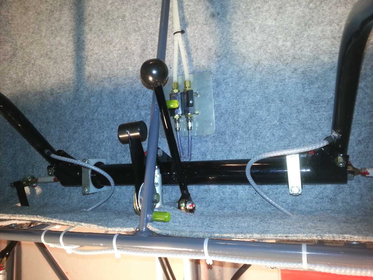
screw thread end up flush with the nut which looks much neater. The
cables that go between the chassis and the control joysticks (for the PTT's)
should ideally be flexible wiring - it's surprising how quickly normal cable
can fail with continuous flexing.
I
used screened cable for the radio signals. Our headset sockets are on the panel
- I made some extra packing panels out of 1.6mm aluminium to go behind the panel
- these not only allow the non rotation washer to be fitted, but also make the
screw thread end up flush with the nut which looks much neater. The
cables that go between the chassis and the control joysticks (for the PTT's)
should ideally be flexible wiring - it's surprising how quickly normal cable
can fail with continuous flexing.
I used some nicer LED based warning indicators - brighter, long lasting and less susceptible to vibration damage.
I also fitted a USB socket to easily connect GPS units and made a supply conditioner for it with suitable filtering. There are four standoff posts to allow each pilot to easily attach a sub-panel to the front of the main panel with their GPS mounted on it.
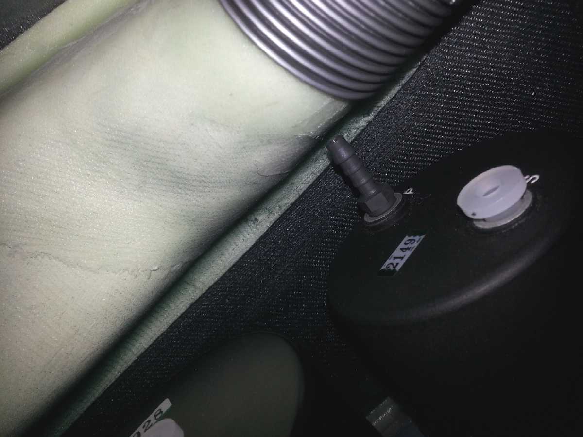 The
adaptor on the ASI to connect the tube to the pitot on ours must be a 90 degree
item, the straight one (supplied) would hit the air vent ducting. We have also
been advised to use a filter on the static ports connections for the ASI, VSI
and Altimeter - I will be using an air filter off a radio controlled car.
The
adaptor on the ASI to connect the tube to the pitot on ours must be a 90 degree
item, the straight one (supplied) would hit the air vent ducting. We have also
been advised to use a filter on the static ports connections for the ASI, VSI
and Altimeter - I will be using an air filter off a radio controlled car.
The coloured rings on the ASI should be in Indicated Air Speed (IAS) - well, for the BMAA version anyway- not sure about the LAA version. The value published are in Calibrated Air Speed (CAS). Therefore you cannot do the rings until the ASI has been calibrated during the first flight testing, then convert the CAS values into IAS. I found out just before wasting time sticking them on!
The glovebox has a peculiar flap of material on it - I thought it must have some special purpose but apparently not.
The Rotax 912 tacho coil produces one pulse per revolution. If you have the same VDO tacho and Hobbs unit as us, it should be programmed for PULSE mode with 1.0 pulses per revolution (P01.00).